Full-Size Split Vibrotactile Headrest CAD Package
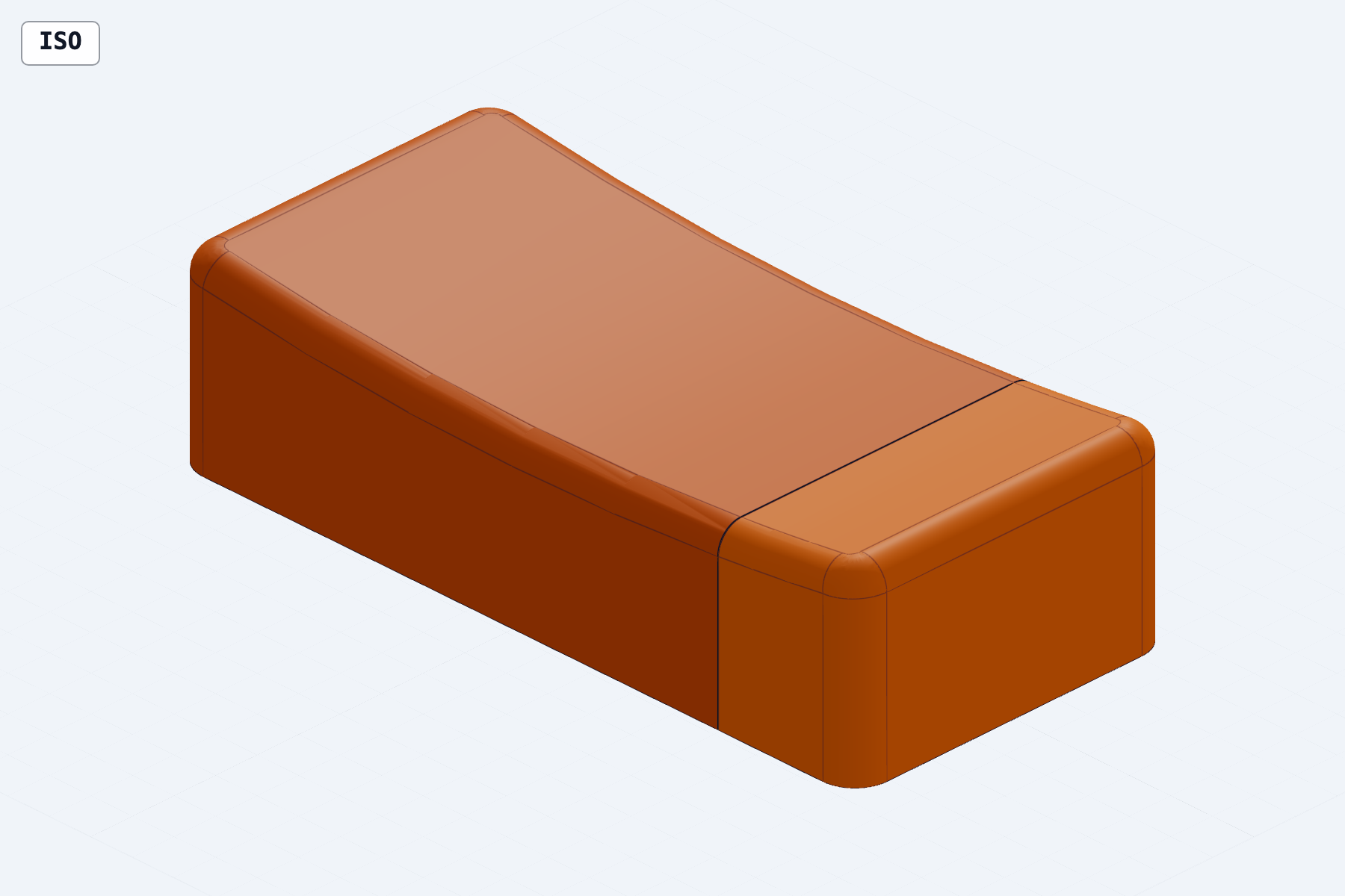
A STEP-first 300 × 140 mm headrest enclosure split for 256 mm printer beds, with editable source, manufacturing exports, a BOM, print guidance, and digital geometry validation.
How it was made
The publisher’s ingredients and steps. Unlisted details are unknown. Copy this text kit to your agent to adapt it.
Models
- Not recorded · OpenAI · execution · Codex
Agent
Codex
Pinned skills
- earthtojake/text-to-cad/skills/cad ↗Commit
fdbb4b4fb62d95ae298cfe9a46fdc7092bdaf423 - earthtojake/text-to-cad/skills/step-parts ↗Commit
fdbb4b4fb62d95ae298cfe9a46fdc7092bdaf423 - earthtojake/text-to-cad/skills/cad-viewer ↗Commit
fdbb4b4fb62d95ae298cfe9a46fdc7092bdaf423
References
- Published brief and result ↗document
Existing result context and its stated limits.
- Recorded execution prompt ↗document
Original reusable prompt; preserved unchanged.
- validation-report.md ↗document
Published evidence used to reconstruct the ordered workflow.
- bom.md ↗document
Published evidence used to reconstruct the ordered workflow.
- print-guide.md ↗document
Published evidence used to reconstruct the ordered workflow.
Tools and APIs
- build123d
Create the parametric Python CAD source included in the published package.
- CAD inspection tools
Inspect STEP topology, part bounds and deterministic joint geometry.
- CAD Viewer
Inspect assembly snapshots and exported models as requested in the published prompt.
Ordered steps
Model the split enclosure
Reconstructed workflow from the published prompt and available result artifacts; this is not a recorded sequence of agent turns. Use the recorded dimensions, off-centre seam, printed pins, structural spine and underside panel. Represent the actuator and sensor as labelled reference envelopes.
Export the manufacturing package
Generate the assembly and individual parts as STEP plus printable STL/3MF, with editable source, BOM and assembly guidance.
Verify digital geometry
Use the validation report to check body and printer-bed bounds, seam gap, connected solids, spanning fasteners, pin clearance and actuator clearance; inspect assembled and exploded views.
Keep the physical boundary
The report validates geometry only. Printing, received-part fit, load, vibration retention, temperature and human-use suitability still need physical validation.
About
A STEP-first 300 × 140 mm headrest enclosure split for 256 mm printer beds, with editable source, manufacturing exports, a BOM, print guidance, and digital geometry validation.
Exact prompt
Hidden characters, if present, appear as Unicode escapes$cad
Create a complete, STEP-first parametric CAD package for a full-size enclosed vibrotactile headrest. Use the installed text-to-CAD skill, build123d Python sources, CAD inspection tools, mandatory snapshots, and CAD Viewer. Do not stop at a concept or ask me to model individual parts manually.
## Product geometry
Units: millimetres.
Coordinate system:
- Origin at the centre of the assembled footprint
- X = 300 mm product length
- Y = 140 mm front-to-back depth
- Z = upward from the closed underside
Overall body:
- Assembled footprint: 300 × 140 mm
- Maximum height: approximately 77.75 mm
- Rounded rectangular plan with R14 vertical corners
- Shallow concave head-contact surface generated by a 1000 mm radius cylinder centred at Z = 1068 mm
- Lowest head-contact point: Z = 68 mm
- Apply a continuous R10 fillet around the upper head-contact perimeter
- The object must look like a compact enclosed pillow/headrest, not a bench or open test fixture
Internal cavity:
- Hidden underside cavity: 214 × 112 × 49 mm
- Cavity spans Z = 4 to Z = 53
- Rounded cavity corners: R10
- Preserve at least 15 mm nominal material between the cavity ceiling and the lowest head-contact point
## Split construction
The finished 300 mm body must fit printers with a 256 × 256 mm bed.
Split the body at X = +90 mm with a nominal 0.30 mm seam gap:
- Primary shell: approximately 239.85 × 140 × 77.75 mm
- End cap: approximately 59.85 × 140 × 77.75 mm
- Keep the central head-contact and actuator region entirely inside the primary shell
- The seam must remain outside the actuator’s Ø104.5 mm maximum tab envelope
Align the shell sections with two removable printed pins:
- Pin diameter: 6.0 mm
- Pin length: 19.2 mm
- Matching horizontal bores: Ø6.4 × 20 mm
- Pin positions: X = 90, Y = ±36, Z = 60
- Export one pin model; two copies are required
The seam must be retained redundantly by both the internal spine and underside service panel. Adhesive must not be the primary structural connection.
## Structural actuator spine
Create a removable PETG spine that bridges the shell seam:
- 210 × 100 × 10 mm
- Rounded corners: R8
- Installed against the cavity ceiling
- Six Ø4.5 mm clearance holes at:
- X = -75, +60, +100
- Y = ±42
- Matching shell insert envelopes: Ø6 × 8 mm
- The X = +100 fasteners must retain the end cap
- Two Ø3.4 mm strain-relief holes at X = +55, Y = +8 and +34
The actuator is a Dayton Audio TT25-8 Puck:
- 8 Ω
- 20 W RMS / 30 W peak
- Frequency range: 20–80 Hz
- Approximately Ø67 mm lower body
- Maximum mounting-tab sweep: Ø104.5 mm
- Overall height: approximately 24.6 mm
- Six supplied #6 surface-mount screws
Represent the actuator as a clearly labelled reference envelope centred beneath the spine. Do not invent its exact six-hole pattern. Leave its mounting area solid for transfer drilling or pilot holes taken from the received physical actuator.
## Structural service panel
Create a one-piece underside panel that also bridges the seam:
- 240 × 132 × 4 mm
- Rounded corners: R12
- Matching body recess: 242 × 134 × 5 mm
- Four Ø3.4 mm clearance holes at X = ±105, Y = ±61
- Add Ø6.2 × 1.5 mm underside recesses for low-profile screw heads
- Matching shell insert envelopes: Ø5.5 × 8 mm
- Add a rounded gasket groove:
- Outer boundary: 226 × 118 mm
- Inner boundary: 220 × 112 mm
- Depth: 0.6 mm
## Cable and sensor interfaces
- Rear-centre passive cable exit: Ø8 mm at Z = 30
- Outer grommet recess: Ø14 mm
- Leave a 2.5 mm retaining lip
- Add a labelled 30 × 30 × 2 mm accelerometer reference envelope at X = +55, Y = 0, against the cavity ceiling
- Only the actuator, passive cable, strain relief, sensor, fasteners and structural spine belong inside
- Amplifier, power supply, Raspberry Pi and audio interface remain external
## Required outputs
Create parametric Python sources and export:
1. Full engineering assembly
2. Primary shell
3. End cap
4. Structural service panel
5. Actuator spine
6. Alignment pin
For every printable part, generate:
- STEP as the primary artifact
- 3MF
- STL
Use descriptive filenames and native labels. Include an assembled view and an exploded engineering view showing the shells, pins, spine, panel, actuator envelope and sensor envelope.
## Validation
Verify programmatically that:
- The assembled body is 300 × 140 × approximately 77.75 mm
- Every individual printable X/Y envelope fits within 256 × 256 mm
- Each shell section is one connected closed solid
- The seam gap is 0.30 mm
- The spine crosses the seam and has fasteners on both sides
- The service panel crosses the seam and has fasteners on both sides
- The pins have 0.40 mm nominal diametric clearance
- The seam does not intersect the actuator envelope
- The actuator envelope clears the installed service panel
- No cavity, insert envelope or fastener breaks through the head-contact surface
Generate and visually inspect snapshots of:
- Assembled isometric
- Top
- Front
- Bottom with panel installed
- Bottom with panel removed
- Exploded assembly
- Seam and alignment-pin detail
Repair any visible or geometric failure, regenerate all affected artifacts, rerun validation, and return the final files, measurements, snapshots and CAD Viewer links.
Clearly state that CAD checks do not prove physical load capacity, print quality, vibration retention, actuator fit, temperature safety or suitability for sleeping or human use.Download the result
Technical details and provenance
- Provider
- OpenAI
- Model
- Not recorded
- Agent
- Codex
- Published
- Publication
- community